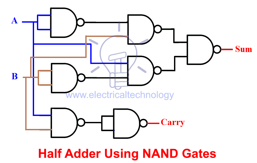
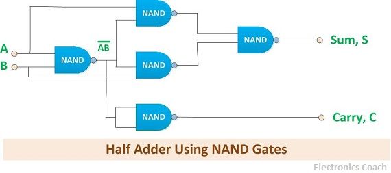
circuit diagram of half adder using nand gate
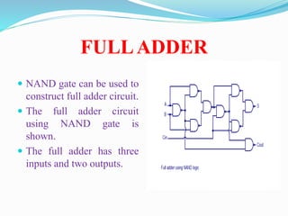
Similar to the half adder a full-adder can also be realized using universal gates ie the NAND and NOR gates. Simulate in Quartus b.

Creating A Full Adder Circuit Using Nand Gates Eeweb
HALF ADDER USING MUX Show circuit diagram.
. The half adder adds two binary digits called as augend and addend and produces two outputs as sum and carry. It is usually done using two AND gates two. Feb 01 2020 Updated.
FA is an easy. The implementation of half adder. XOR is applied to both inputs to produce sum and AND gate is applied to both.
Minimum NANDNOR Gates - Realization For ExORExNorAdderSubtractor gateoverflowin. Implementation of Half Adder using NAND gates. Draw the diagram of a Half Adder HA.
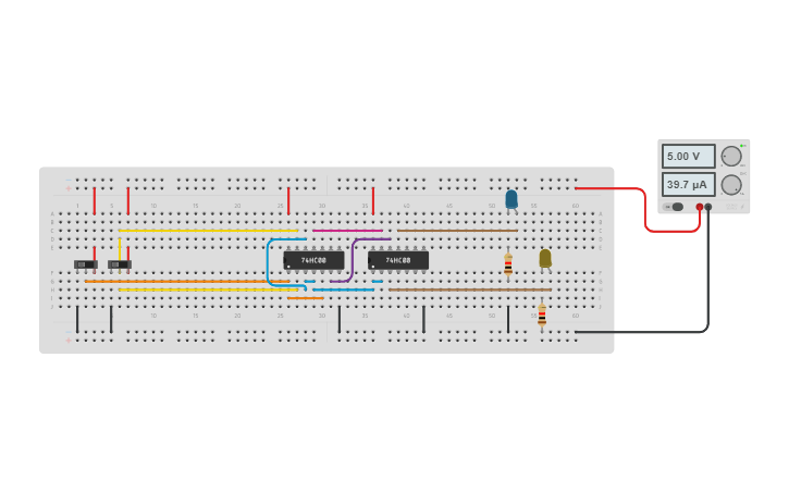
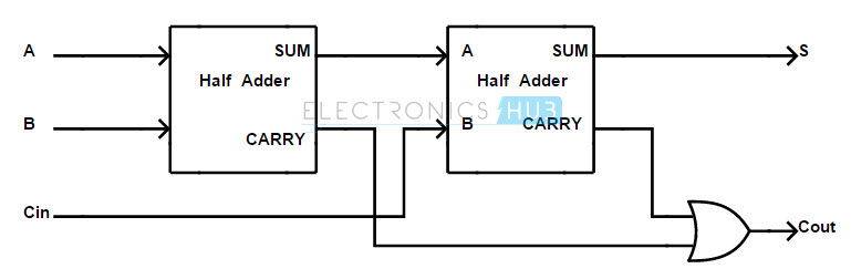
The 5V DC supply is applied to the circuit. A Full-adder circuit adds three one-bit binary numbers A B Cin and outputs two one-bit binary numbers a Sum S and a carry Cout. Multiplexers in Digital Logic.
FA using NAND Gates. Draw the logic diagram. Calculator logic circuit diagram gates using bit binary adder true link 74hc instructables series.
The full adder circuit diagram using two half-adders is shown below. This circuit employs seven NAND gates to create a half adder circuit. The half adder circuit is built using XOR gate IC 7486 and logic AND gate IC and both are two-input logic gate ICs.
Combinational circuits using Decoder. Nand subtractor gates nor adder half using minimum exor gate realization. 9 rows A NAND gate is one kind of universal gate used to execute any kind of logic design.
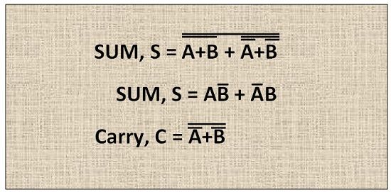
Draw K-maps using the above truth table and determine the simplified Boolean expressions- Also Read-Half Subtractor. Two whole half adder circuits in addition to an OR gate. When the 5V VCC and ground is supplied to the logic.
The A and B inputs. Draw K-maps using the above truth table and determine the simplified Boolean expressions- Also Read-Half Subtractor. Half adder using nand gates 0 Stars 320 Views Author.
A0 B0 constitute the binary digit inputs. Apr 07 2021 Add members. The implementation of half adder.
The FA circuit with the NAND gates diagram is shown below. A full adder circuit uses 7486 XOR IC 7408 AND IC and 7432 OR IC all the three ICs are the two-input logic gates. Draw the logic diagram.
How To Build A Touch. Draw diagram for the Half Adder V. Half Adder Using Basic Gates Show circuit diagram.
Determine Boolean functions in NAND Gate form iv.
Half Adder Circuit And Full Adder Circuit Using Nand Gates
Digital Logic Minimum Nand Nor Gates Realization For Exor Exnor Adder Subtractor


Half Adder Using Nand Gate Tinkercad

Creating A Full Adder Circuit Using Nand Gates Eeweb
Binary Adder Subtractor Construction Types Applications
Nand Gate
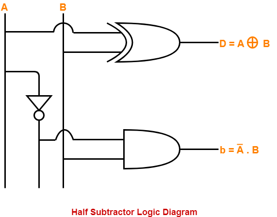
Half Subtractor Using Nand Gates Gate Vidyalay

Lab

What Is Half Adder Half Adder Using Nand Gates Nor Gates Truth Table Electronics Coach


Half Adder Using Nand Gate Tinkercad

File Half Adder Using Nand Gates Only Jpg Wikimedia Commons
Half Adder Using Nand Gate Multisim Live
What Is Half Adder Half Adder Using Nand Gates Nor Gates Truth Table Electronics Coach

Half Subtractor Using Nand Gate Youtube
What Is Half Adder Half Adder Using Nand Gates Nor Gates Truth Table Electronics Coach